How the compact fuel bunker was created for Winkler – precisely planned, digitally integrated, reliable in operation
When Winkler Baugesellschaft wanted to modernize an existing system, there was a crucial problem:
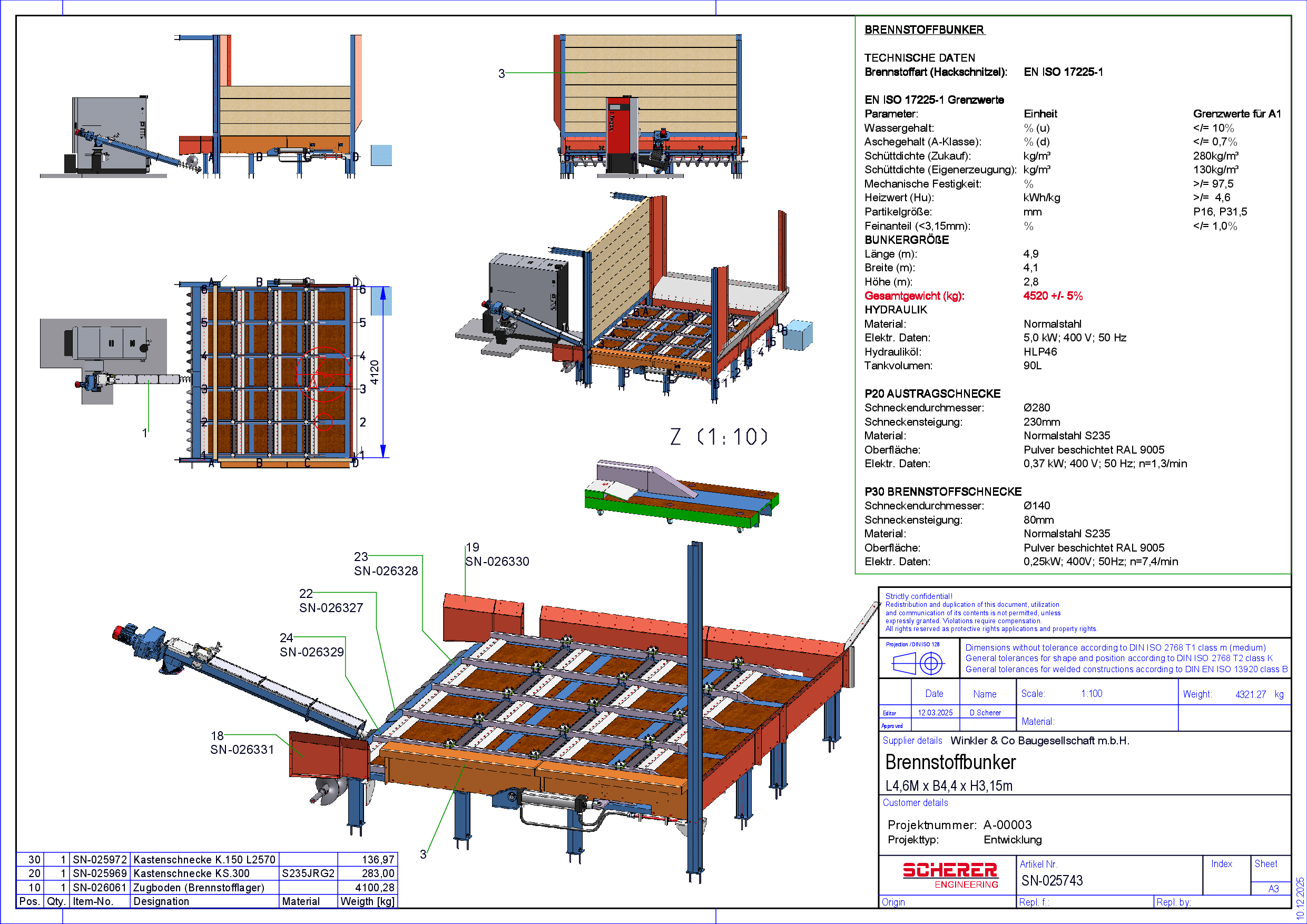
No suitable fuel bunker with automatic discharge was available for the existing boiler technology.
Standard solutions were either too large, too long or could not be integrated into the very confined space of the plant room.
This is exactly where the project began.
Initial situation – no series product fitted the reality
The manufacturer of the boiler system explained that such a bunker with integrated automatic discharge technology did not exist in the series portfolio.
This made it clear that a customized solution was needed:
- little space required
- fits completely into the inventory
- works together with the existing boiler technology
- runs reliably and with low maintenance in the long term
The spatial situation made the task even more challenging.
Without a digital inventory, collision-free planning would not have been possible.
Digital basis – complete 3D laser scan
Before even one component was designed, a complete 3D laser scan of the technical room was carried out.
A digital, millimeter-precise image of the real environment was created from the generated point cloud.
On this basis:
- the steel construction modeled
- the moving floor is integrated
- the screw technology is placed collision-free
- Hydraulics, motors, service routes and access rooms taken into account
The result was a fully digitally planned overall integration that fitted exactly into the existing building.
The real innovation: a moving floor without the usual loss of installation space
Classic moving floor systems usually require a drive area behind the bunker because the hydraulic cylinder is located axially behind the moving floor.
This lengthens the body considerably – a problem in confined installation spaces.
The developed solution solves this problem completely:
✔ Closed ladder frame construction
✔ Two hydraulic cylinders positioned at the side
✔ Synchronous drive without axial protrusion
The bunker therefore only requires the actual floor space, i.e:
- 4.9 m length
- 4.1 m width
- 2.8 m height
The system can therefore be integrated into rooms where standard technology simply cannot be installed.
Screw conveyor technology – continuous fuel supply
The bunker uses two screw levels:
- P20 – Box auger KS.300, Ø 280 mm, 0.37 kW
- P30 – Fuel auger K.150, Ø 140 mm, 0.25 kW
Both screws were positioned in such a way that:
- Interfering edges are avoided
- uniform discharge is guaranteed
- Maintenance work remains easily accessible
Hydraulic module – powerful and perfectly integrated
The hydraulic unit:
- 5.0 kW motor power
- 90 liter tank capacity
- Medium HLP 46
- Design for segmented moving floor panels
This allows the moving floor to be moved smoothly, controlled and powerfully – even under full load.
Realized complete system – precise planning, fast implementation
According to the project report, the system was successfully put into operation in winter 2025 and ran stably, smoothly and efficiently from day one.
The overall system includes:
- Compact steel bunker
- Segmented moving floor
- Screw technology for fuel delivery
- Hydraulic module
- Complete digital integration into the existing boiler technology
- Production documents (STEP, PDF, DXF) incl. weight and parts lists
Result
The Winkler fuel bunker shows what modern system integration can achieve:
- Extremely compact design due to lateral hydraulics
- Precise digital planning via 3D laser scan
- Reliable fuel discharge thanks to optimized screw technology
- High-quality steel construction
- Complete functional integration into an existing system
- Short installation and commissioning time
The project proves:
When standard technology reaches its limits, there is room for real engineering work.
Fuel bunker onLinkedIn