
Technical data:
cooling capacity: approx. 500-1000kg/h
Dimensions: 900x900x1917mm
airlock: 0.2kW
Discharge system: pneumatic

Technical data:
Cow power: approx. 3000-5000kg/h
Dimensions: 1800x2200x2950mm
airlock: 0.2kW
Discharge system: pneumatic
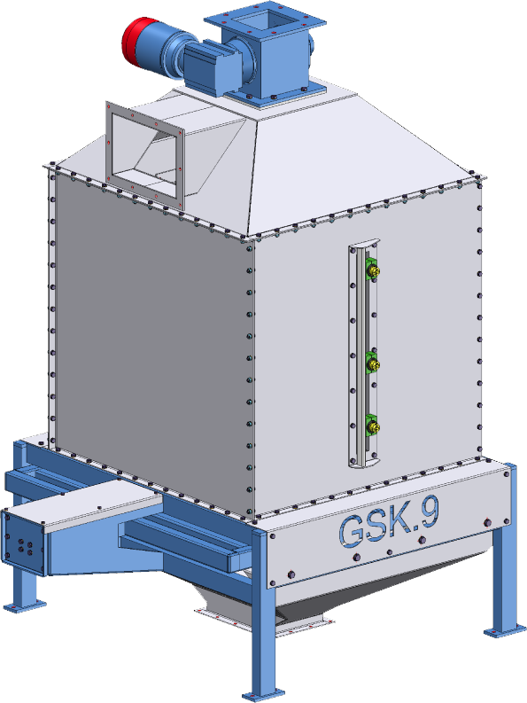
General description of the counter-current cooler
Execution:
- Radiator construction made of 3mm thick sheet metal construction
- Base frame made of profile disarming tube in solid steel, welded construction
- pneumatic discharge system in saddle construction to avoid product-specific bridge formation, good air flow and complete residual emptying
- Transparent maintenance opening for easy refrigeration access
- 3pc adjustable level sensors Min, Max and overfill protection
- Cell wheel lock in stainless steel with coupled gear motor 0.75kW
- Adjustable air control flap with manual adjustment (standard), automatic adjustment available as an option
- Exhaust air connection with rectangular cross-section on the side of the radiator roof
General function description of the counter-current cooler:
All our coolers are based on:
1) Discharge system pneumatically operated with position sensors for discharge control
2) Refrigeration room for granules or granules similar products with square cross-section, full-surface discharge system
3) 3pcs level sensors mounted on the radiator door
4) Electronic Temperature Sensor 4… 20mA for temperature monitoring without evaluation (signal processing is carried out by on-site control)
5) Sprinkler system optionally available
6) Rotary lock on the radiator roof with directly coupled gear motor
The swinging floor discharge works fully on a surface and thus prevents bridge formation and ensures uniform cooler emptying.
The saddle construction results in a discharge geometry that is characterized by
- good air flooding with optimized cooling effect and
- good tightness against granules and similar products with similar properties
The exhaust air nozzle arranged on the side of the radiator roof includes a manually adjustable snap bolt adjustment for correcting the air volume flow.
This exhaust port is used to connect the on site cooling air to be provided.
Usually this exhaust air connection is used in combination with a further exhaust air system consisting of, fan, cyclone as pre-separator m. rotary valve and, if necessary, possibly a subsequent filter system.
The correct system design is the responsibility of the responsible plant planner.
The non-binding execution guideline for air demand is:
Air demand:
2000m3/h cooling air with ambient temperature< 20°C per tonne of refrigerated goods/hr at a product inlet temperature of approx. 80°C.
Depending on the ambient conditions of summer/winter as well as the product entry temperature, deviations may occur and must be taken into account separately.
The radiator filling takes place from above through the cell wheel lock. The presence of a rotary valve is essential for cooling operation, as this alone can prevent the supply of external air.
The pellets thus entered fill the cooling chamber until the 2nd level sensor is reached.
During the entire filling period, ambient air is pulled from below through the product layer thickness and the refrigerated material is cooled down to ambient temperature.
When installing a cooler in doors, care must be taken to ensure sufficient fresh air supply from the outside in order to avoid a vacuum in the building!
The outlet temperature of the refrigerated material should not exceed 5°C above ambient temperature to ensure sufficient stability and strength of the final product.
Too high outlet temperature of the refrigerated material can lead to instability and product decay due to re-absorbed condensate!
The cooling time depends on the set distance between the 1st and 2nd level sensors.
The switching distance is freely selectable by the operator within defined limits.
Greater distance means: longer dwell time = better cooling result
Shorter distance means: shorter dwell time = worse cooling result
The switching distance is to be chosen in principle in such a way that a sufficient cooling result results within the limits described above with sufficient lead time of the refrigerated material.
Too much switching distance leads to overfilling of the cooler, the system resistance of the connected air system increases, the cooling capacity decreases, units to be conveyed are to be stopped.
On average, a switching distance between the sensors of approx. 30-50cm is sufficient for proper cooling. With consciously higher filling, the connection fan must be dimensioned with a higher suction power.
Attached to the transparent inspection opening, the 3pc level sensors are mounted on an adjustment rail.
Function of the 2nd level sensor:
“Start” of the cooler discharge
Function of the 1stlevel sensor
“Stop” of the cooler output
Function of the 3rdfilling stan sensor
“Overfill protection” to protect the cooler


