Hydraulic chain‑floor system for biomass & bulk materials
Robust discharge solutions for receiving bunkers, silos, and storage bins
Modular chain‑floor for controlled biomass discharge
Hydraulic chain‑floor systems are a proven solution for the safe and uniform discharge of biomass, wood chips, and other difficult-flowing bulk materials. Conventional discharge systems quickly reach their limits, especially in large receiving bunkers, storage bins, or deep installations. The hydraulic chain floor operates actively and controllably – independent of material moisture, inhomogeneity, or bridging.
Scherer Engineering designs, engineers, and implements hydraulic chain‑floor systems as customized system solutions – precisely adapted to material properties, bunker geometry, and downstream conveying equipment.
Operating principle of the hydraulic chain‑floor system
The chain floor consists of several parallel push frames that are cyclically moved by hydraulic cylinders. Through defined lifting motions, the material is gradually transported toward the discharge point. The movement is controlled and reproducible, ensuring a consistent material flow.
The hydraulics allow for high forces while maintaining smooth operation. This makes the system suitable even for wet, compacted, or inhomogeneous biomass with high resistance.
The timing and stroke sequence are designed to achieve a stable discharge rate without tearing the material or releasing it abruptly.
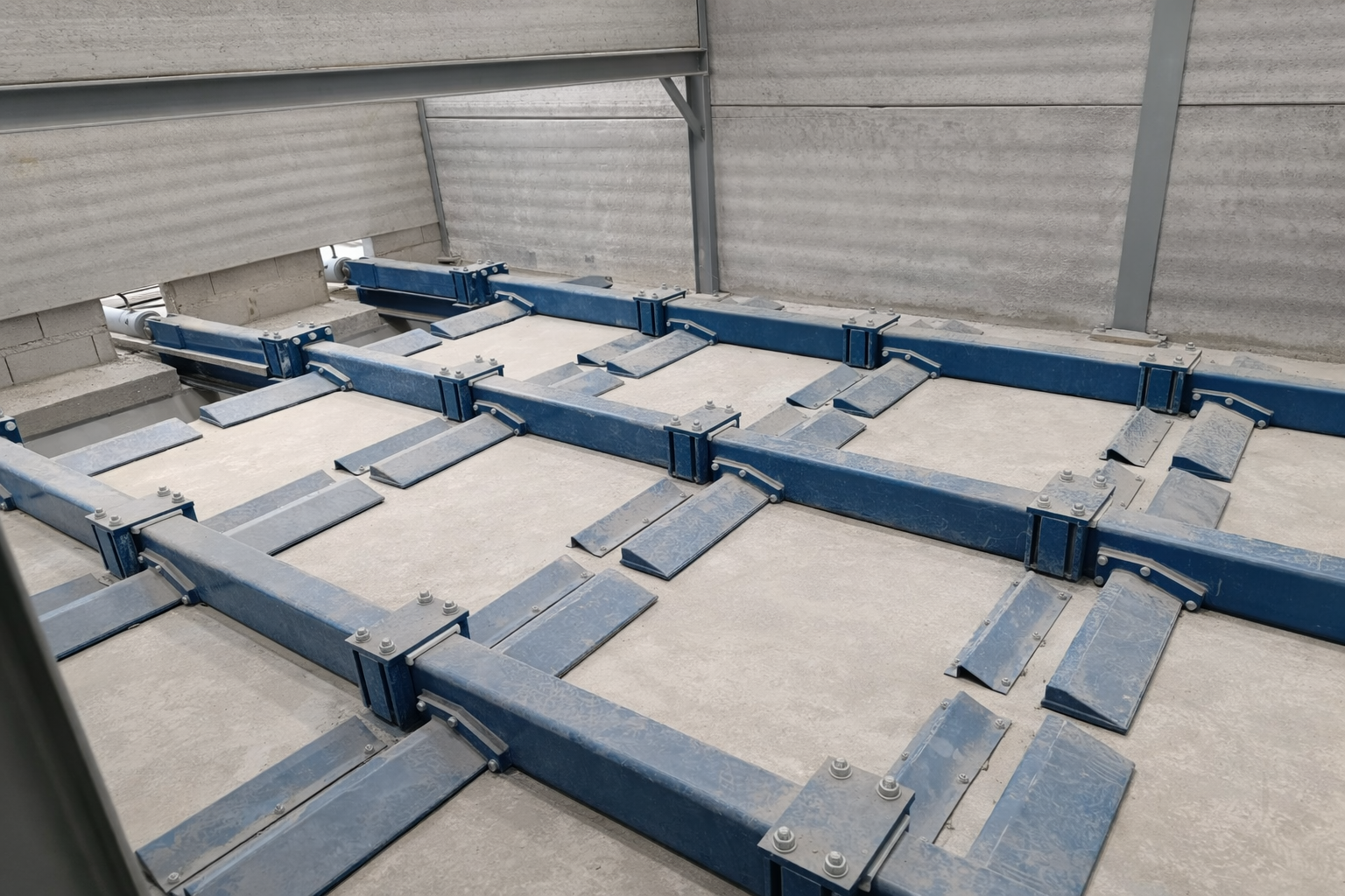
Detailed view of the modular chain‑floor construction
System layout and components
The hydraulic chain‑floor system is modular in design and essentially consists of the following components:
Chain‑floor / push‑frame construction Robust, welded steel frames designed for high continuous loads and long service life.
Sliding and guide elements Defined bearing surfaces for controlled force transmission and minimized wear.
Hydraulic drive High-performance hydraulic cylinders with coordinated stroke and operating pressure.
Hydraulic unit Central unit supplying the cylinders, integrated or externally positioned depending on the project.
Substructure & integration Designed for installation in concrete bunkers or steel structures, adjustable and assembly-friendly.
Control & automation Stroke sequence, cycle times, and interlocks are adapted to the process and safely monitored.
Technical design (example system)
The design of a chain‑floor system is project-specific. The following data show a realized reference configuration:
System dimensions: Length 12,400 mm, Width 4,850 mm, Overall height 1,000 mm
Stroke of push frames: 800 mm
Drive: hydraulic
Maximum operating pressure: 200 bar
Hydraulic cylinders: Differential cylinders, cylinder diameter approx. 160 mm
Number of chain‑floor units: 3
Hydraulic unit: 30 kW
Suitable for material moisture up to 70 %
Discharge capacity: approx. 5–10 t/h, depending on material and process conditions
These technical parameters are precisely adapted to the specific application during project planning.
Chain‑floor B4825 L12400 – up to 10 t/h discharge capacity at 70 % moisture
Advantages of the hydraulic chain‑floor system
Uniform, controlled discharge
High operational reliability, even with challenging materials
Reduced downtime
High mechanical robustness
Maintenance-friendly design
Scalable in length, width, and capacity
Precise adaptation to process and material
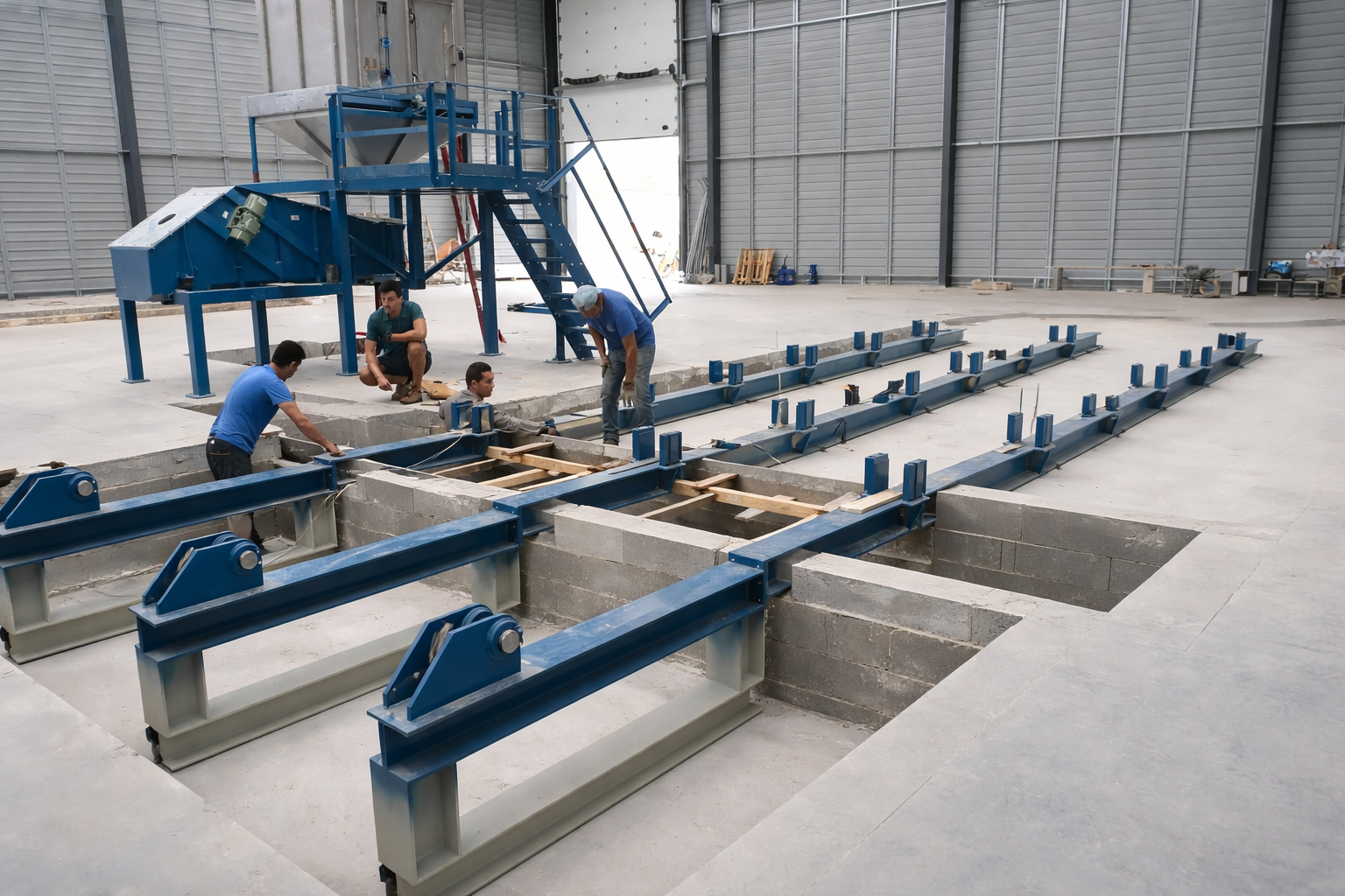
Installation and integration into existing plants
Hydraulic chain‑floor systems can be integrated into both new and existing plants. Typical areas of application include:
Receiving bunkers for biomass
Storage bins and intermediate storage
Low‑height silos
Discharge systems upstream of conveyors, screw feeders, or dosing systems
Thanks to the low overall height and modular design, adaptation to existing concrete or steel structures is usually straightforward.
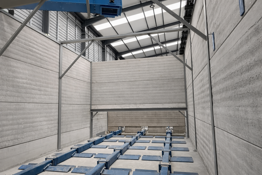
Installation of the push frames and chain‑floor units in the receiving bunker
Project workflow at Scherer Engineering
Analysis of material, process, and as‑built conditions
Technical design and layout planning
Design and fabrication of the chain‑floor system
On‑site assembly and commissioning
Handover including technical documentation
Receiving bunker with hydraulic chain floor – material feed for biomass plants
Inquiry & Contact
Are you planning a receiving bunker or looking for a reliable discharge solution for biomass or bulk materials? We are happy to assist you with the design of a hydraulic chain‑floor system – from the initial concept to fully operational implementation.
Contact us for a technical consultation or a project-specific design.
Die hydraulischeZugbodenanlage entstand aus einer konkreten betrieblichen Problemstellung in einer bestehenden Biomasseanlage. Ziel war es, eine zuverlässige und gleichmäßige Austragung auch bei anspruchsvollen Materialeigenschaften sicherzustellen und gleichzeitig die bestehende Bunkergeometrie weiter zu nutzen.
Die Entwicklung der Zugbodenlösung, die konstruktiven Entscheidungen sowie die Umsetzung vom Bestand bis zur betriebsbereiten Anlage wurden in einem begleitenden Projektbericht dokumentiert.